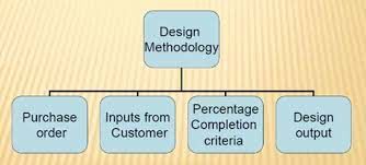
1.What is design methodolgy ?
Image shows steps in Design methodolgy
1. Purchase order : Purchase order is the order from the customer for start of work.
2. Inputs from customer : For BIW fixture designing the customer demands some requirements to be fulfilled in it viz., functional requirements, preferred standard components, car products, layout, ergo data, weld study, standard detailing templates.
3. Percentage completion criteria : Percentage completion criteria is followed in the designing stages and dispatch stages of the welding fixtures.
0-25% - Input and concept design
25-40% - Concept approval and simulation check
40-85% - Design freezing and detailing
85-100% - Check and final dispatch
4. Design output : The output is 3D models and 2D drawings of the tools.The are two types of tools :
1. Unitized tools : (multiple units on a common base) requires two types of drawing sheets.
2. Non unitized tools : Tools that can stand alone and can be completely detailed in a layout sheet.
2. What are the inputs required from the customer to start designing a fixture?
The inputs required from the customer to start designing a fixture are ;

Image shows the inputs from customer
a. Functional requirements : It explains the requirement for which the fixture will be used like if it is a welding fixture, hemming fixture, checking fixture, storage racks.
b. Preferred standards : Preferred standards explain the standards to be followed for the components which includes
1. Standards like ABB, NAAMS, DESTACO, ZYTRAN.
2. Standard parts like L-blocks, risers, retainers, pins.
3. Components like slides, clamps, cylinders, switches, sensors, weld gun, tip dressers, tool changers.
c. Car products : Car products include
1. GD&T of the parts.
2. Part list.
3. CAD files of car parts.
4. Clamp plan.
5. Product assembly process sheet.
d. Layout : Layout provides information of flow of parts, station pitch, robot stations, accessories like tool changer and tip dresser, subassembly links, platform height, loading and unloading sequence heights.
e. Ergo data : Ergonomics refers to the study of human behaviour and movements. Ergo data provides information of loading height, working safety zone of the operator etc.
f. Weld study : Weld study includes weld gun details, weld matrix and weld points i.e. geo weld points and respot weld points.
3. What is the input we get from car products?
The input we get from the car products are:
1. GD&T : GD&T provides information of locating pins, rest, clamps, dumps and slide information of each station. Also, it provides the sequence of opening of clamps, dumps and slide stroke information.
Image shows GD&T applied for the component
2. Part list : Part list contains the list of the parts to be assembled in fixture i.e. the part no., part name, revision of the part, part thickness.
Image shows part list
3. CAD files of car parts : The customer provides the 3D & 2D CAD files of the BIW parts from which the BIW fixture designing procedure will be carried out.
4. Clamp plan : Clamp plan provides the location of pins, rest, clamp, dumps etc.. The clamp plan shouldn't be changed without seeking permission from the customer.
Image shows clamp plan
5. Product assembly process sheet : Product assembly sheet is like a flow chart or process flow diagram explaining how the child parts are to be assembled to form sub assemblies and how the sub assemblies are assembled to form the final BIW assembly.
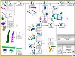
Image shows product assembly process sheet
4. What is the clamp plan?
Image shows clamp plan for assemblying the component
Clamp holds the car part firmly and prevent the part from distortion while carrying out the operation.
Clamp plan describes the location of pins, rest, clamp, dumps etc. to be placed on car part during assembly.
Clamp plan shouldn't be changed without the consent from the customer.
It gives the details of the exact X,Y and Z coordinates on which the clamps, rest, pins, dumps etc of the fixture are to be placed upon the part as shown in the image below.
5. What is the purpose of a layout?
Layout is a sheet which explains the entire assembly layout and the space constraints of the process.
The layout information includes
1. Flow of parts : Layout explains the flow of parts from one station to another station.
2. Station pitch : The distance between two stations representing space constraints of a layout.
3. Robot stations : Robot stations and position of the robots in the space constraint.
4. Accessories like tool changer and tip dressers: The locations of accessories in the layout where the robot has to pickup and place the tool from its location.
5. Sub assembly links : Sub assembly links describes the link between subassembly fixture and the main assembly lines.
6. Loading/unloading sequence heights : The height of the platforms and its loading and unloading sequence.

Image shows the layout
6. What is Ergo data?
In case of manually operated fixtures the company provides a pictorial representation of the standard data according to which the operating heights and the operating distance of the fixture should be provided for the ease, comfort and safety of the operator.
Ergonomics refers to the study of human behaviour and movements.
In short, ergo data provides information of loading height, working safety zone of the operator etc.
Image shows ergo data
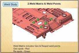
7. What do you understand by weld study?
Weld study includes weld gun details, weld matrix and weld points i.e. geo weld points and respot weld points.
Weld gun details includes the type of gun to be used on that particular spot for welding.
Weld matrix and weld points includes no. of spots to be welded, sequence of weld and the position of weld to be done onto the component, geo spot weld points and respot weld points.
8. What are the criteria for percentage completion in the designing stage? Explain it in detail.
Percentage completion criteria is followed in the designing stages and dispatch stages of the welding fixtures.
0-25% (Input and concept design) :-
The initial stage of designing fixture involves understanding the customer input describing their requirememts and preparing the design concept as per the customer requirement.
25-40% (Concept approval and simulation check) :-
The customer approves the design or suggests some design changes they require if any. After the design approval from the customer the fixture design will be subjected to simulation checking.
40-85% (Design freezing and detailing) :-
After successfully passing the simulation checking the design concept is freezed and finalised and the detailings of the fixture assembly and its child part components is done.
85-100% (Check and final dispatch) :-
The fixture assembly and the components manufactured are then inspected and finally dispatched
9. Brief about output in design?
After completion of the fixture design the output documentations should be provided to the customer. The output is 3D models and 2D drawings of the tools, user manual data, functioning of the tools, switches, sensors and cylinders.The are two types of tools :
1. Unitized tools : (multiple units on a common base) requires two types of drawing sheets.
2. Non unitized tools : Tools that can stand alone and can be completely detailed in a layout sheet.
The output should compile following points:
a. Approved standard components are to be used wherever possible.
b. Design must be as simple and economical as possible.
c. Design must comply with safety and ergonomic requirements.
d.Design must provide for controlled and damaged free handling of product.
e. Adequate error proofing must be incorporated into each design by providing proximity switches, rough locators etc.
f. The weight of the moving parts must be kept to a minimum while maintaining maximum strength.
g. Frames and structures are to be kept simple and sturdy.
h. Design clearance and accessibilty for routine maintenance and services.
i. Designer is responsible to validate clamps and all weld guns.
j. Motion control must be considered on any moving equipments.
10. What do you understand by structuring a design tree? How does it reduce errors during the design process?
Structuring a design tree implies to a process whjere all the assemblies and parts are named in a specific standard. Different customers have different set of standards to structure a design tree.
It helps us to identify a specific part or assembly, as to which project, tool or unit it belongs to.
This helps us to avoid errors during design study, manufacturing, assembly, inspection etc..
If the parts or assemblies are not named properly or the design tree is not structure properly, it will create confusion to understand the design and may create major possiblities of making an error.
Naming of a fixture or a unit or a part, gives information as to which zone or project or assembly do they belong.
It can help us to identify the quantity of items of same type or different types that are being used in an assembly.
11. What are units? mention 5 types of units.
A unit is a device that forms a specified functions, in a BIW fixture assembly. Multiple units are mounted together on a base unit and the combined assembly forms a BIW fixture.

Units are classified into 2 types:
1. Unitised tools
2. Non unitised tools
1. Unitised tools : A unitised tool unit possesses multiple parts which together a unit.
Unitised tools are further divided into 2 types :
a. Simple units
b. Complex units
a. Simple units : Simple units are units which are simple to design and manufacture.
The types of simple units used in BIW fixtures are;
1. Fixed pin unit : Fixed pin unit is a unit designed to locate the car panels using pins.
2. Retractable pin unit : A retractable pin unit is a unit designed to locate the car panels using pins, but the entire pin package parts will be mounted on the retractable pneumatic cylinder.
3. Rest unit : A rest unit is a unit designed to rest / support the car panel using NC blocks / Mylars / Rest.
4. Clamp unit : A clamp unit is a unit designed to clamp / hold the car panel with NC blocks / mylar / rest by using a pneumatic clamp cylinder.
5. Sensor unit : A sensor unit is a unit designed to sense the car panel using electrical sensor. This signal from the sensor will be fed to the PLC and so the next process will be executed by this signal.
6. Rough Locator unit : A rough locator is a part designed to guide the operator, to locate the car panel on to the pin accordingly. A rough locator can be of standard part or make part.
7. Base unit : A base unit is a unit designed to mount all the other units (clamp unit, pin unit, rest unit etc.) of the tool, also other necessary parts for a tool like pneumatic valve box, trunking cable path will also be mounted on to a base unit.
b. Complex unit : Complex units are the units which are complex to design and manufacture.
1.Slide unit : Sliding unit consists of a sliding cylinder which slide the entire panel along the guide rails towards the sensor unit for carrying out the operation.
2. Dump unit : A dump unit is used whenever there is a requirement to hold the car part in a particular geometrical constraint.
2. Non unitised tool : A non unitised tool is a single standalone unit itself like stands, take out trolleys, conveyers, turn tables, some grippers.
12. Describe fixed pin units and their purpose?
Fixed pin unit is a unit designed to locate the car panels using pins.
A fixed pin unit consists of pins, blocks, retainers, shims, blade and risers.
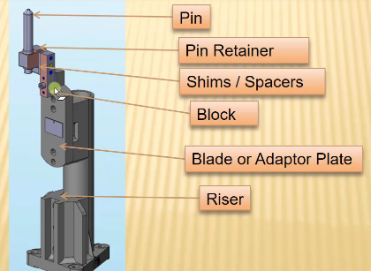
Image : Fixed pin unit
The purpose of fixed pin units is to restrict rotational as well as translational degrees of freedom. The fixed pin unit restricts translational motion along two axes and one rotational motion along the axis of panel.
Pin should be placed on the exact coordinate which otherwise would lead to a rejected car panel assembly.
13. What are the different parts of a fixed pin unit?
A fixed pin unit primarily consists of
Image : Fixed pin unit
a. Riser : Riser is a structure upon which the locating pin, toggle clamp, rest and clamp mylars are mounted.
b. Blade : Blade is plates mounted on the riser upon which clamps, arms etc. are mounted.
c. Shims : Shims are used to adjust the stack up tolerances and comes in the the sizes of 0.1mm, 0.2mm and 0.5mm. Two directional shims are used to position the pin accurately in a fixed pin unit.
d. Pin : Pin is used for the location purpose of the panel.
e. Pin retainers: Pin retainer is a unit used to hold the pin in its place.
14. What is the purpose of making a rest unit and describe its parts?
A rest unit is a unit designed to rest / support the car panel using NC blocks / Mylars / Rest.

Image : Rest unit
A rest unit consists of
a. Riser : Riser is a structure upon which the locating pin, toggle clamp, rest and clamp mylars are mounted.
b. Blade : Blade is plates mounted on the riser upon which clamps, arms etc. are mounted.
c. Shims : Shims are used to adjust the stack up tolerances and comes in the the sizes of 0.1mm, 0.2mm and 0.5mm. Only one directional shims are used in a rest unit.
d. NC blocks/ mylars : Mylars are the parts upon which the entire panel rests. There are two types of mylars : rest unit mylars and clamp unit mylars. Rest mylars are the parts where the car panel rests and clamp mylars are the parts which holds the car panel.
15. What are basic fundamentals to design a sensor unit?
A sensor unit is a unit designed to sense the car panel using electrical sensor. This signal from the sensor will be fed to the PLC and so the next process will be executed by this signal.

Image : Sensor unit
Fundamentals of sensor unit design are:
1. Every single panel which are being welded in a tool should be sensed.
2. Each panel should be sensed by 1-2 sensor depend on the size of panel. Preferred to be in diagonal opposite ends of panel.
3. Every panel should be mounted in a 3 direction adjustable way in general.
Types of sensor used in general are :
16. What is a rough locator unit and what are the basic points to be considered while designing it?
A rough locator is a part designed to guide the operator, to locate the car panel on to the pin accordingly. A rough locator can be of standard part or make part.

Image : Rough locator unit
Fundamentals of rough locator design :
1.Rough locators should be placed at the edges of car panel, which it has to guide.
2.Rough locators has to be placed in the same angle of the car part edge with a minimum distance of 2-5mm from the edge of the car part.
3. Rough locators should guide the panel in pin arresting direction.
4. Rough locators should start guiding the panel before 10-15 mm to the start of pin engagement.
5. Rough locators should be designed with entry angle for car part entry.
6. Rough locators should be designed with 2 slots to mount for easy adjustments.
7. The slots should be in the direction of car part guiding.
17. What is a base unit and describe it's parts?
A base unit is a unit designed to mount all the other units (clamp unit, pin unit, rest unit etc.) of the tool, also other necessary parts for a tool like pneumatic valve box, trunking cable path will also be mounted on to a base unit.

Image : Base unit
A base unit primarily consists of
a. Base plate : A base plate is a structure upon which various tappings and holes are machined for mounting the pin unit, rest unit, clamp units etc.
b. Pedestal : Pedestals are the parts of base unit which joins base plate to the floor plate.
c. Floor plate : A floor plate is a unit which is mounted on to the ground and upon which the entire base unit stands.
d. Valve box : A valve box is a unit which supplies pressurised air to the cylinders and also takes back as and when required.
e. Trunking channels : Trunking channels are the ducts which carries pneumatic hose pipes and electrical connections.
f. Eye bolts : Eye bolts are used to lift the entire base unit during shifting purpose.
18. What is a dump unit and what are its function?
A dump unit is used whenever there is a requirement to hold the car part in a particular geometrical constraint.
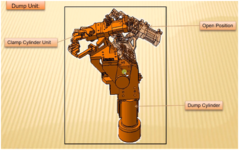
Image : Dump unit
Dump unit is used for functioning incase the car panels for assembling are to be provided with a particular constraint and hence dump unit cylinder comes into play for clamping in a desired way.
Hence dump units are complex in design and construction.
19. What is a slide unit? Mention where slide units are commonly used?
Sliding unit consists of a sliding cylinder which slide the entire panel along the guide rails towards the sensor unit for carrying out the operation.
It is most commonly used in situations when there is space constraints to use many units or panels to be assembled are more.
A slide unit consists of a cylinder which moves the panel to be assembled along the guide rails from the closed position to the open postion where the welding operation is performed and the panel is stopped by the stopper and locked when the desired position is determined by the sensor. After finish the welding operation the panel moves back to the closed position.
Image : Slide unit