OBJECTIVE
To develop Class A surface and master section input of a car interior B pillar provided into a functional product design following the OEM design standards using CATIA V5 Surface workbench following the injection moulding principles.
ABSTRACT
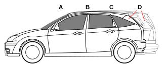
Pillars are the vertical or near vertical supports of a car's window area or greenhouse, designated respectively as the A, B, C or (in larger cars) D-pillar, moving from front to rear, in profile view.
While designing plastic trims, functionality, safety and styling are crucial factors. These factors will also influence the vehicle sales in the market. Also the design should be done in such a way that, it is manufacturable in a cost efficient manner. Here the B pillar interior plastic trim was designed by following the injection moulding principles.
Trim applications require a variety of essential plastic material properties:
The project report deals with the steps and procedures followed while creating a plastic interior B pillar trim for cars designed using CATIA V5 surface workbench. It explains the method I followed for creating the main tooling axis, side core axis, Class B surface, Class C surface and final closed body creations. It also explains the draft analysis performed to check the manufacturability of the product using injection moulding.
PROCEDURE
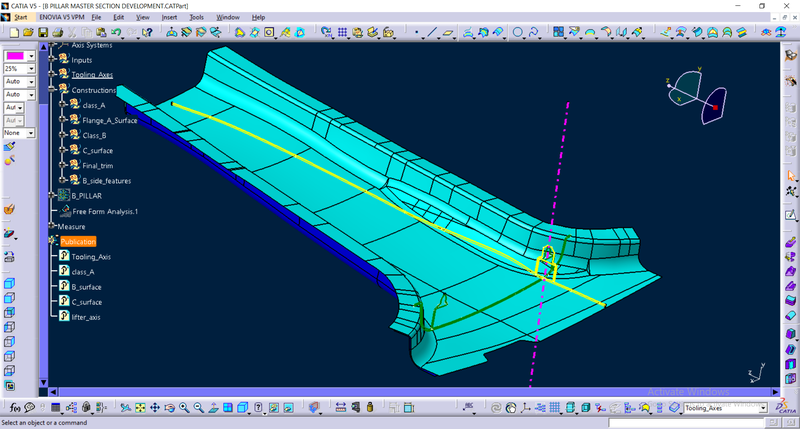
In Automotive industry there will be a dedicated team who will perform the aesthetic designing of various components including the whole vehicle. They will create various concept sketches after ideation. After that, they will also create a Class A surface of the product. This class A surface is then passed over to the NPD CAD team. They will initially inspect the Class A surface in order to check if the design is manufacturable or if it is following the engineering principles. If there are any issues about the design, they will contact the product design team and will ask to modify the Class A surface in order to solve the problem. Here I received the Class A surface of the B pillar interior plastic trim with master section as shown below.

Class A surface and master section
At first, I did some inspection on the surface to check if any open areas are present and did a draft analysis for checking the manufacturability. I found some open areas by using ‘boundary’ option and rectified it by myself and joined it with a merging distance of maximum 0.003 mm.
Creation of the flanges were the next procedure. For that purpose master sections are provided. I created two flanges using the master section on the class A surface.
Flanges
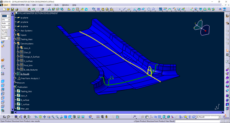
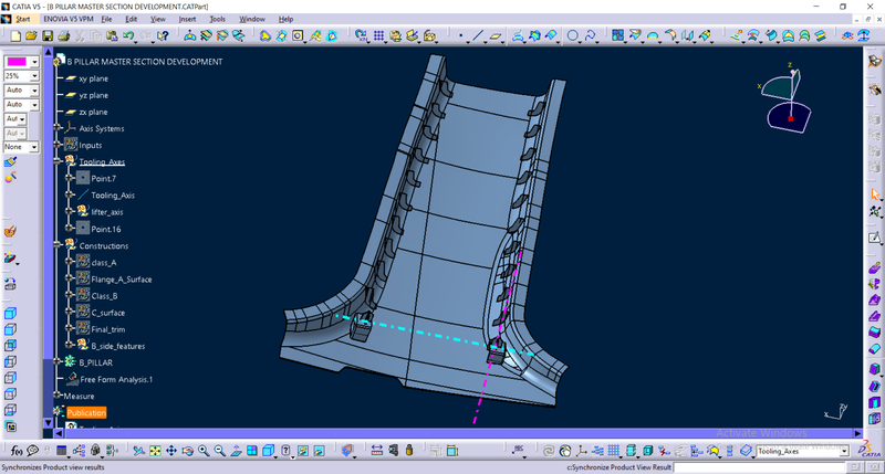
Creation of the main tooling axis is the next step. During injection moulding process core is moved along the tooling axis. Here we have to use the master section for engineering features for creating the tooling axis.
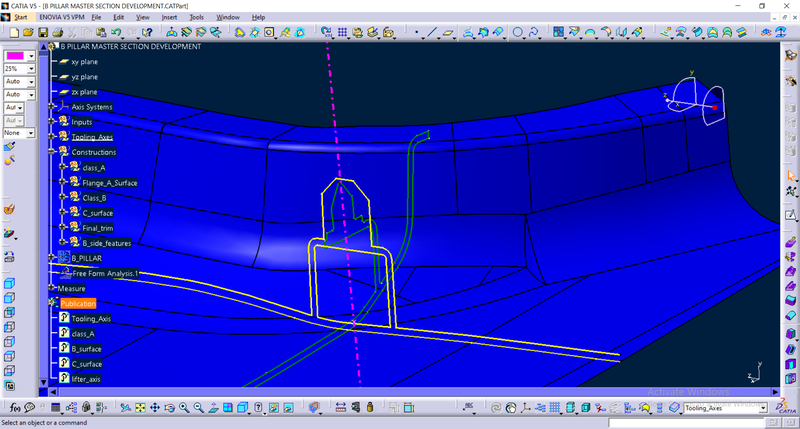
Main tooling axis (pink dotted line)
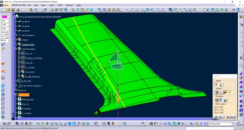
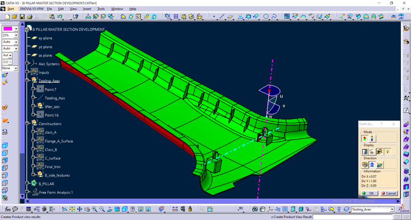
Draft analysis for checking the manufacturing feasibility
Draft analysis was performed for 3 degree draft angle with main tooling axis as reference. Areas with less than 3 degree are bit difficult and costly to manufacture. So we have to rectify those areas maximum as possible. Here the green colour represents areas with draft angle greater or equal to 3 degree. Blue colour represents areas with draft angle less than 3 degree and greater than zero. If the draft angle is red those areas will be less than zero degree draft angle.

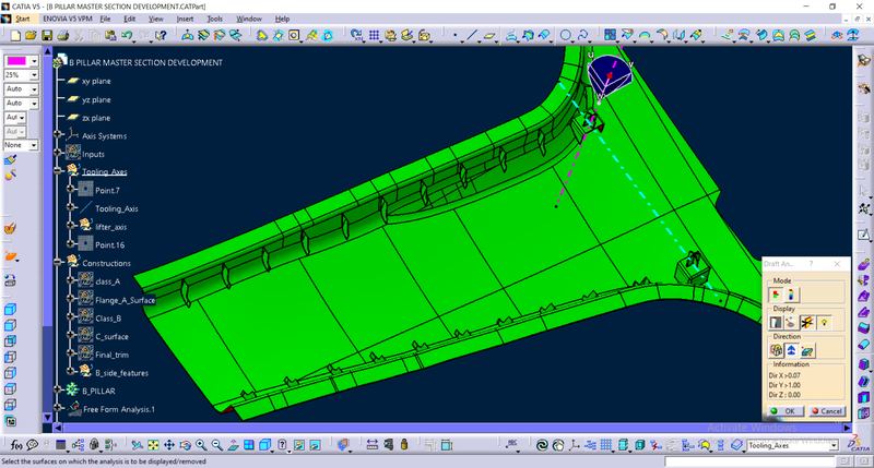
Draft analysis

Here, there was a small patch of blue which represents area with draft angle less than three degree. So in order to rectify that we have to contact the styling team whom designed the class A surface. A draft analysis report was sent to styling team for that purpose.
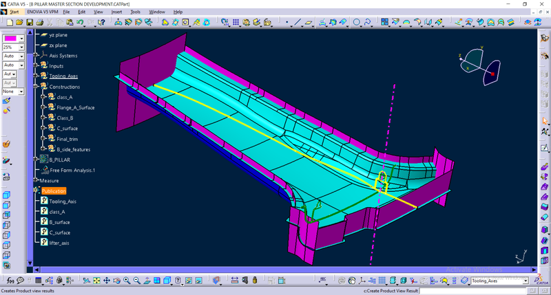
B surface
After receiving the rectified class A surface, next step is the creation of B surface. According to the master section the thickness of the part is 2 mm. So I offset the class A at a distance of 2mm inwards. Patches on the B surface were rectified and joined together.
B surface (cyan colour)
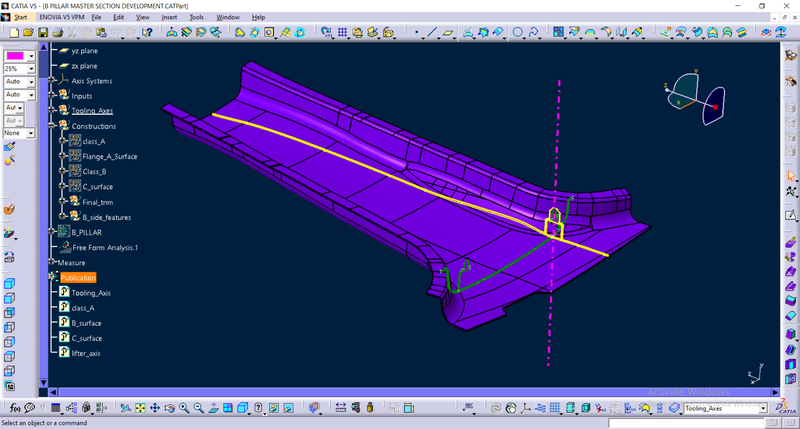
C surface
C surface was created along the boundary of A surface using sweep tool. C surface was swept with an inclined angle outwards with respect to main tooling axis, so that flash occur along the boundary of B surface.. If it is inclined inwards into the B surface, we will need to design the core such a way that flash will occur along the edges of Class A surface. It will drastically reduce the aesthetics of the final product.
Class C surface (Pink)
Final closed body creation
Both A and C surfaces were joined together and trimmed it with the B surface for final closed surface creation. The closed surface was inspected for openings using ‘Boundary’ tool. There were no openings and the surface was perfect.
Closed surface
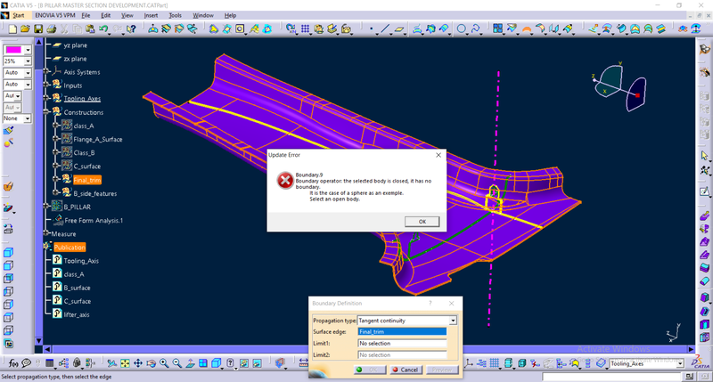
Inspection for openings using ‘boundary’ command
Draft Analysis result
Draft analysis was successfully performed with a 3 degree draft with respect to the main tooling axis.
Draft analysis
Doghouse, rib and four way locator creation
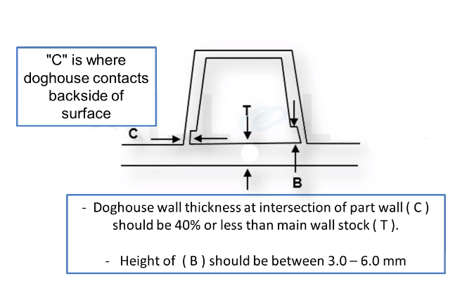
In the master section, doghouse with a four way locator is given. At first we have to create the doghouse.
Doghouse & Four way locator
Dog house is an engineering feature used in plastic trim design. The primary function of a dog house is to avoid sink marks on the class A surface which may occur due to features such as a thick screw boss or rib on the back side of Class A. So the best possible solution is to increase the height and decrease the cross sectional thickness of the ‘legs’ by using a dog house. We can also use them for solving necessity of large length features such as a screw boss which may requires large length sometimes. We can use a dog house and make a screw boss above it on such situations. We can also use them for making features which are perpendicular to the main tooling direction.
Design Guidelines
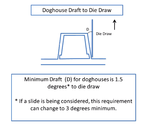
Also the distance between the top walls at opening should be minimum 12mm.
Thus, following the guidelines, a dog house required for B pillar was designed using CATIA V5 Surface workbench as shown in the images. Thickness was applied to the surface using part design workbench. Necessary draft angle and fillets were also applied on it. A 4 way locator was also designed above the Dog -house according to the master section. Then one more doghouse was placed opposite to it with a minimum distance of three times the side wall width of doghouse. Otherwise the lifter for moulding the doghouse inner walls can’t be moved along lifter axis. Draft analysis was successfully performed with 0.5 degree draft angle. Four way locators will be cleared along the main tooling direction.

doghouse with four way locator on it
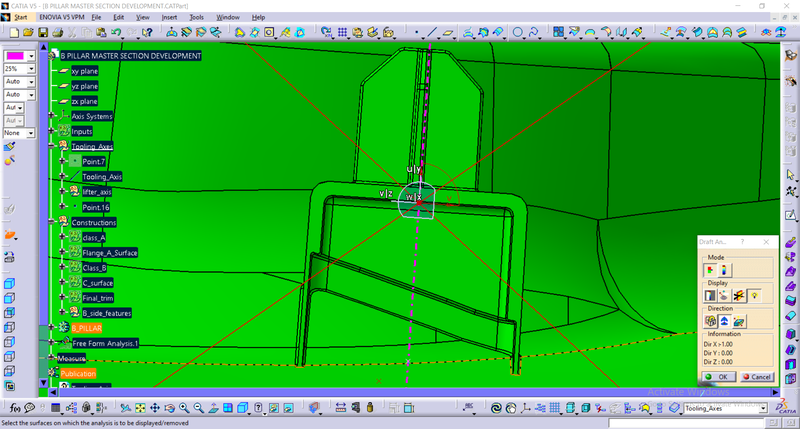
Draft analysis of doghouse inner walls (normal view)
Ribs
Ribs provide a means to economical stiffness and strength in moulded parts without increasing overall wall thickness. They also facilitate:
1) Locating & arresting components of an assembly.
2) Providing alignment in mating parts.
3) Acting as stops or guides for mechanisms.
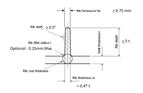
Rib Nomenclature
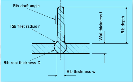
Design rules for rib creation
Very tall ribs are prone to buckling under load. If you encounter one of these conditions, consider designing two or more shorter, thinner ribs to provide the same support with improved mould ability (see figure). Maintain enough space.
between ribs for adequate mould cooling: for short ribs allow at least two times the wall thickness.
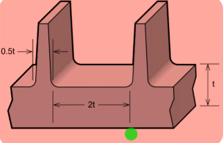
Thus following all the design guidelines, ribs were created at both sides with minimum 50mm gap as shown below
Ribs
Draft analysis of the ribs were successfully performed with 0.5 degree draft angle.
Draft analysis on ribs
Thus B pillar interior plastic trim was successfully designed with given class A surface and master section using Catia V5 surface workbench , which can be manufactured using plastic injection moulding.
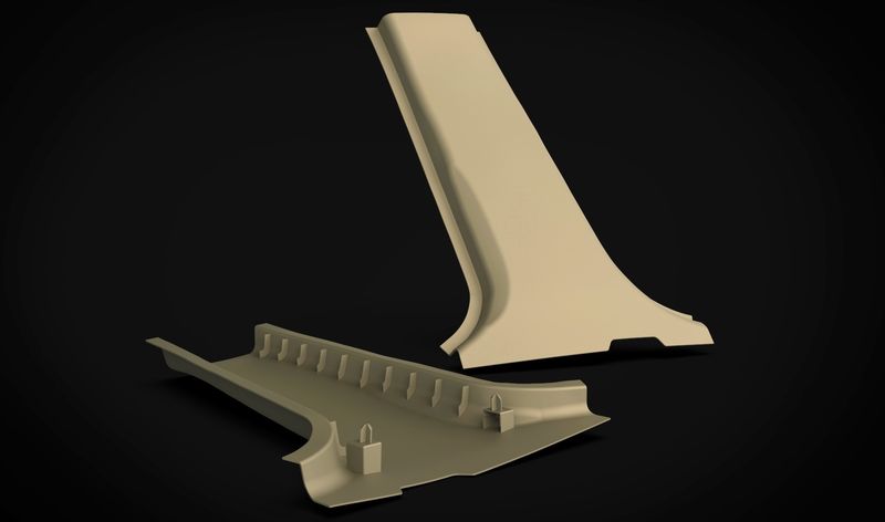
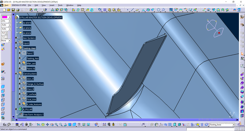
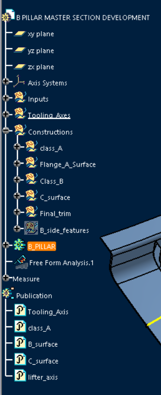
Design tree

Rendering of the B pillar
References:
2) https://www.trinseo.com/Industries/Automotive/Interiors/Trim
3) https://en.wikipedia.org/wiki/Pillar_(car)
My Linkedin profile: www.linkedin.com/in/jophinlouis/